
Theory
Profile Levelling
This method is also called as longitudinal levelling or sectioning. The object of the leveling deration is to determine the undulations of the ground surface along a predetermined line, which is usually the centre line of a road, railway, canal or pipe line. The line of section may be a single straight line or may corner of a series of straight line changing direction or connected by curves.
The levelling operation always start from a bench mark and end of the bench mark. If the permanent bench mark is not near the line of section, flying level may be run from the permanent bench mark to establish a bench mark near the line of section.
Procedure
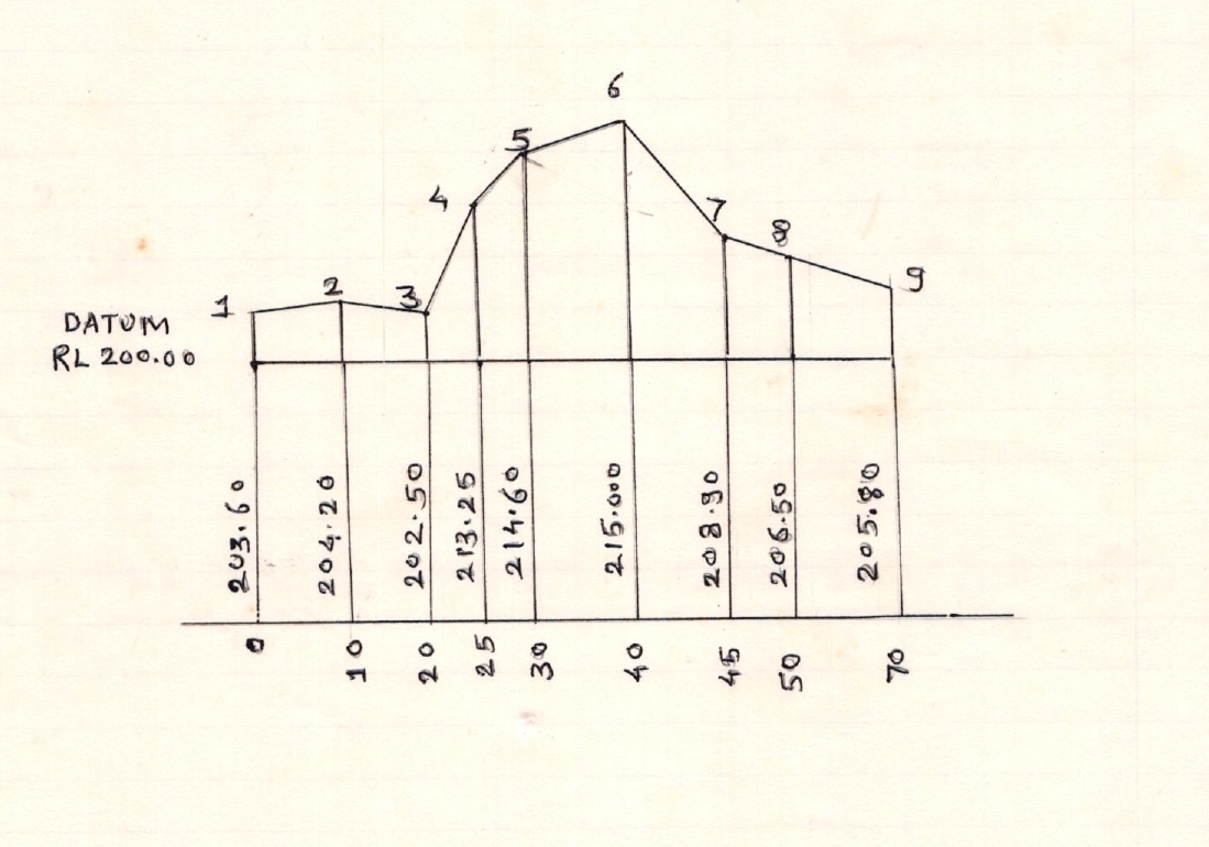
Let AB the line of section on which staff station are marked on the ground at every 10 to 30 m. The level is setup on firm ground at some suitable position (L1) to the right or left of the section line so as to command a large number of points on the line and accurately leveled. A back sight is taken on the bench mark to determine the reduced level of the plane of collimation (H.I.) and entered in the back sight column of the level book. Having stretched the chain in line from A. The staff reading are taken at the starting point ‘A’ 10 m point and entered in the Intermediate sight columns against the respective change along the line which are recorded in the distance column, when it is found by necessary to shift the instrument on account of the length of sight exceeding about 100 m or the further point not being possible to be observed owing to the irregular of the ground. The staffman when selected a suitable change point (C.P.I.) on firm ground or permanent object and the fore sight is taking on it and entered it in the fore sight column. The change point may or may not be on the sectional line. The instrument is taken moved forward and setup on the firm ground at L2 as before the back sight is then taken on the ground of change point just established to find the elevation of new plane of collimation changing and reading are then continued as before until the reading is obtained at the last point B. The bench mark which have been previously established before they should be established at the end of every ten chains for further reference. They may be used as the chainage point whenever possible. In order to checked the reduce level of these bench marks they should be connected with the permanent bench mark be taking by fly level. The fore and back bearing of the section line should be taken and recorded in the appropriate column.
Diagram
Cross sectioning
Cross section are the section run at right angle to the centre line and on either side of it for the purpose of determining the lateral out line of ground surface. For thus purpose on the centre line. The length of the cross section depends upon the nature 30 m to 60 m on each side of the center line and in the case of a railway zero to 300 m or more on either side of the centre line.
If the cross section are short, they are set out by eye. e.g. cross section for a road. If long they are set out by the optical square box sentant or theodolite. They are serially numbered from the beginning of the cente line and fare then taken simultaneously with the longitudinal section. They may be taken with level, hand level, Abney level or theodolite.
Cross section by level
To begin with the line is set out perpendicular to and an either side of centre line the station on the centre line where it is desired to take the cross section. The staff is held at each 10 m point and other points of approxi cable change in slope which have been previously marked on the line by means of whites the readings are then taken with a level and the distance of staff points measured with the tape left and right the centre station.